Category:Hardware
Pages specific to the laptop hardware. For a gentle intro, see XO; for the various models of XO hardware, see the subcategory XO.
Subcategories
This category has the following 23 subcategories, out of 23 total.
D
F
H
T
Pages in category "Hardware"
The following 200 pages are in this category, out of 323 total.
(previous page) (next page)8
A
B
C
D
- D-Pad Toothpick Modification
- Datasheets
- DCON Testing
- DCON Testing/lang-ko
- DCON/lang-ko
- Debugging Open Firmware Startup
- Deployment Guide/Workbook
- Desmontaje
- Developers program/lang-fr
- Developers program/lang-ja
- Developers program/lang-ko
- Disassembly
- Disassembly bottom
- Disassembly design
- Disassembly top
- Disassembly/Archive
- Display
- Display Power
E
F
G
H
- Hardware
- Hardware design
- Hardware design/lang-es
- Hardware design/lang-ko
- Hardware Drivers
- Hardware Drivers/lang-ko
- Hardware ideas
- Hardware modification
- Hardware Power Domains
- Hardware Power Domains/lang-ko
- Hardware specification
- Hardware specification 1.5
- Hardware specification 2.0
- Hardware specification/lang-de
- Hardware specification/lang-fr
- Hardware specification/lang-it
- Hardware specification/lang-ja
- Hardware specification/lang-pt
- Hardware specification/lang-ru
- Hardware Testing
- Hardware uniqueness
- Hardware uniqueness/lang-es
- Hardware uniqueness/lang-ko
- Hardware/lang-ja
- Health Hardware
- How to Damage a FLASH Storage Device
- Huawei Ideos S7
M
N
O
P
- Per-Activity Power Usage
- Peripherals
- Peripherals/USB GPS Receiver
- OLPC Wiki - Mirror:Photo gallery
- Pictures/lang-it
- Pictures/lang-ja
- Port Address
- Power Management Software
- Power Management/lang-es
- Power Management/lang-ja
- Power Management/lang-ko
- Programming the Altera FPGA
- Programming the SPI FLASH
- Projects/SpikerBox
- PyDuino
R
S
- Samsung Galaxy Tab 3
- School server/lang-es
- Screws
- SD and USB FLASH Drive Performance
- Secure Digital card
- Serial adapters
- Simple repairs
- SPI FLASH Recovery for XO-1.5
- SPI FLASH Recovery for XO-1.75 Using CForth
- SPI FLASH Recovery for XO-1.75 Using JTAG
- SPI FLASH Recovery for XO-4 Using CForth
- SPI FLASH Recovery for XO-4 Using JTAG
- SPI FLASH Recovery/XO-1
- SPI FLASH Recovery/XO-1.5
- SPI FLASH Recovery/XO-4
- Storage Indicator
- Stress test
- Support
- Support FAQ/Mouse, Touchpad
- Support new
- Suspend and resume
- Suspend and resume OFW
Media in category "Hardware"
The following 200 files are in this category, out of 372 total.
(previous page) (next page)-
1.75 serial connector.png 1,369 × 1,121; 2.76 MB
-
10w iv.png 579 × 290; 15 KB
-
10w pwr.png 576 × 282; 13 KB
-
802.11s 1.jpg 392 × 237; 12 KB
-
802.11s 2.jpg 401 × 320; 15 KB
-
802.11s 3.jpg 410 × 105; 6 KB
-
802.11s 4.jpg 372 × 369; 24 KB
-
802.11s 5.jpg 433 × 410; 38 KB
-
AA-dims.jpg 529 × 613; 73 KB
-
AA-front.jpg 597 × 629; 64 KB
-
AA-tilted.jpg 1,023 × 1,388; 197 KB
-
All screws.jpg 466 × 349; 148 KB
-
All screws.png 562 × 305; 204 KB
-
 Aus-EMC.pdf ; 438 KB
-
B1-mikemcgregor-2-small.jpg 710 × 656; 80 KB
-
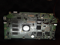 Board1.png 400 × 300; 213 KB
-
CL1 EMC Report.pdf ; 359 KB
-
CL1A Hdwe Design Spec.pdf ; 897 KB
-
CL1B A2 LoadLine.png 542 × 706; 40 KB
-
CL1B B2 LoadLine.png 553 × 796; 48 KB
-
Closeup-J1.png 525 × 529; 503 KB
-
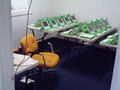 Collab Network Testbed 0099.JPG 1,280 × 960; 291 KB
-
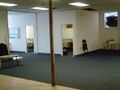 Collab Network Testbed 0101.JPG 1,280 × 960; 227 KB
-
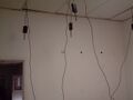 Collab Network Testbed 0103.JPG 1,280 × 960; 163 KB
-
 Collab Network Testbed 0104.JPG 1,280 × 960; 261 KB
-
CPU ejabberd median per conn-old tls-new tls.png 800 × 400; 32 KB
-
DC Sample Connector 01.JPG 1,024 × 683; 107 KB
-
DC Sample Connector 02.JPG 1,024 × 683; 104 KB
-
DC Sample Temp Connector.JPG 1,024 × 683; 97 KB
-
DCON system.png 821 × 497; 64 KB
-
Dpad mod1.jpg 700 × 525; 85 KB
-
Dpad mod10.jpg 688 × 525; 77 KB
-
Dpad mod11.jpg 700 × 525; 87 KB
-
Dpad mod12.jpg 700 × 525; 87 KB
-
Dpad mod13.jpg 700 × 525; 67 KB
-
Dpad mod14.jpg 700 × 525; 66 KB
-
Dpad mod2.jpg 700 × 525; 101 KB
-
Dpad mod3.jpg 700 × 525; 98 KB
-
Dpad mod4.jpg 700 × 525; 95 KB
-
Dpad mod5.jpg 700 × 525; 74 KB
-
Dpad mod6.jpg 700 × 525; 99 KB
-
Dpad mod7.jpg 700 × 525; 96 KB
-
Dpad mod8.jpg 700 × 525; 75 KB
-
Dpad mod9.jpg 700 × 525; 76 KB
-
DSCN0461.JPG 2,592 × 1,944; 945 KB
-
FirstXO3Sugar.jpg 2,144 × 1,608; 530 KB
-
How-to-open.gif 300 × 240; 911 KB
-
Image10.png 683 × 512; 558 KB
-
Image11.png 683 × 512; 566 KB
-
Image12.png 795 × 420; 396 KB
-
Image13.png 862 × 590; 685 KB
-
Image14.png 886 × 598; 572 KB
-
Image15.png 1,749 × 918; 149 KB
-
Image16.png 1,338 × 591; 95 KB
-
Image17.png 1,488 × 807; 86 KB
-
Image4.png 640 × 480; 122 KB
-
Image5.png 640 × 480; 136 KB
-
Infineon closeup.png 303 × 129; 73 KB
-
LaptopPowerB2.pdf ; 84 KB
-
LCD-olpc.png 216 × 144; 1 KB
-
Load avg 5 max per conn-old tls-new tls.png 800 × 400; 37 KB
-
Load avg 5 median per conn-old tls-new tls.png 800 × 400; 36 KB
-
Load avg 5 min per conn-old tls-new tls.png 800 × 400; 34 KB
-
Microscope capture 01.png 160 × 128; 20 KB
-
Microscope capture 02.png 160 × 128; 16 KB
-
MPPT2Dynamics.png 1,067 × 1,499; 165 KB
-
MPPT2Operation.png 1,067 × 1,499; 212 KB
-
MPPT2wAdapter.png 1,065 × 1,499; 162 KB
-
MPPTOperation.png 1,057 × 1,499; 218 KB
-
MPPTwAdapter.png 1,055 × 1,499; 167 KB
-
Multi-Battery Charger.png 962 × 744; 808 KB
-
OLPC cup and magnet 1.png 623 × 844; 916 KB
-
OLPC cup, magnet and coil 1.png 664 × 991; 1.11 MB
-
OLPC guitar probe coil 3b.png 869 × 626; 1.11 MB
-
OLPC input jack.png 406 × 629; 168 KB
-
OLPC microphone -- assembly 1.PNG 1,325 × 819; 75 KB
-
OLPC oscillator 0.PNG 1,360 × 819; 65 KB
-
OLPC oscillator 0.png 2,125 × 1,280; 976 KB
-
OLPC stereo input jack.png 406 × 629; 168 KB
-
OLPC tuning fork oscillation on screen 1.png 1,229 × 922; 2.06 MB
-
OLPC tuning forks 1.png 1,053 × 615; 1.19 MB
-
OLPC vibrating tuning fork 1.png 1,167 × 846; 1.73 MB
-
OLPC vise and coil 1.png 1,082 × 772; 1.08 MB
-
Olpc XO dim-Optimized.png 4,282 × 2,399; 90 KB
-
Olpc XO dimensions.jpg 4,282 × 2,399; 830 KB
-
OLPC-to-Ellisys-to-WLAN.JPG 1,280 × 960; 192 KB
-
OLPC-to-shortUSBcable.JPG 1,280 × 960; 204 KB
-
 Opening-1.jpg 420 × 300; 44 KB
-
 Opening-2.jpg 420 × 300; 45 KB
-
Osc-and-jumpers.jpg 2,048 × 1,536; 822 KB
-
Osc-diagram.jpg 2,048 × 1,536; 713 KB
-
Osc-in-use.jpg 2,048 × 1,536; 759 KB
-
Oscilloscope cabling 1.PNG 4,607 × 2,630; 1.1 MB
-
Oscilloscope cabling 2.PNG 4,886 × 873; 611 KB
-
Oscilloscope cabling 2j.png 2,389 × 2,191; 1.33 MB
-
Oscilloscope cabling 3.PNG 4,907 × 1,716; 1.25 MB
-
Oscilloscope cabling 4.PNG 4,994 × 1,629; 1.05 MB
-
Oscilloscope cabling 5.PNG 4,690 × 2,111; 1.35 MB
-
Oscilloscope cabling 6.PNG 4,836 × 1,832; 1.28 MB
-
Oscilloscope circuit 2.png 5,104 × 1,663; 889 KB
-
Oscilloscope circuit 2c.png 740 × 505; 424 KB
-
Oscilloscope circuit 2d.png 1,092 × 748; 383 KB
-
Oscilloscope circuit 2e.png 986 × 676; 368 KB
-
Oscilloscope circuit 5 1.PNG 1,222 × 516; 221 KB
-
Oscilloscope circuit dimensions 2g.png 1,126 × 624; 114 KB
-
Oscilloscope circuit layout 2j.png 1,198 × 657; 425 KB
-
Oscilloscope enclosure cover 1.PNG 4,790 × 2,647; 777 KB
-
Oscilloscope enclosure left 1.PNG 1,531 × 2,802; 635 KB
-
Oscilloscope enclosure right 1.PNG 3,373 × 3,066; 1.36 MB
-
 Power-button.jpg 480 × 328; 16 KB
-
Resident mem max per conn-old tls-new tls.png 800 × 400; 35 KB
-
Resident mem median per conn-old tls-new tls.png 800 × 400; 37 KB
-
Resident mem min per conn-old tls-new tls.png 800 × 400; 40 KB
-
Serial adapter 3.png 1,425 × 363; 758 KB
-
Serialadapter jumpers.jpg 950 × 598; 172 KB
-
Starting up the XO.jpg 1,024 × 274; 98 KB
-
TEIATH-Α1-DSC01087.JPG 800 × 600; 54 KB
-
TEIATH-Α1-DSC01088.JPG 800 × 600; 67 KB
-
Try6-load avg 1-load avg 5-load avg 15.png 800 × 400; 70 KB
-
Try6-psmem-resident mem-virtual mem.png 800 × 400; 49 KB
-
Try6-users active vs cputime.png 800 × 400; 32 KB
-
Try6-users active vs resident mem.png 800 × 400; 41 KB
-
Try7-load avg 1-load avg 5-load avg 15.png 800 × 400; 82 KB
-
Try7-psmem-resident mem-virtual mem.png 800 × 400; 48 KB
-
Try7-users active vs cputime.png 800 × 400; 34 KB
-
Try7-users active vs resident mem.png 800 × 400; 41 KB
-
Try8-load avg 1-load avg 5-load avg 15.png 800 × 400; 76 KB
-
Try8-psmem-resident mem-virtual mem.png 800 × 400; 49 KB
-
Try8-users active vs cputime.png 800 × 400; 33 KB
-
Try8-users active vs resident mem.png 800 × 400; 40 KB
-
Try9-load avg 1-load avg 5-load avg 15.png 800 × 400; 59 KB
-
Try9-psmem-resident mem-virtual mem.png 800 × 400; 50 KB
-
Try9-users active vs cputime.png 800 × 400; 32 KB
-
Try9-users active vs resident mem.png 800 × 400; 43 KB
-
Verde.png 640 × 401; 196 KB
-
Videodemo.png 450 × 372; 141 KB
-
Virtual mem max per conn-old tls-new tls.png 800 × 400; 36 KB
-
Virtual mem median per conn-old tls-new tls.png 800 × 400; 35 KB
-
Virtual mem min per conn-old tls-new tls.png 800 × 400; 34 KB
-
Vizio BOM.pdf ; 68 KB
-
Vizio bottom half.jpg 1,265 × 1,280; 236 KB
-
Vizio display.jpg 1,280 × 1,258; 172 KB
-
Vizio interconnects.png 907 × 1,259; 154 KB
-
Vizio sandwich.jpg 1,280 × 956; 103 KB
-
Vizio top half.jpg 1,203 × 1,280; 148 KB
-
Vizio touchscreen.jpg 1,280 × 910; 93 KB
-
WhyMPPT.png 1,057 × 1,499; 177 KB
-
XO 1.5 A2 Annotated Motherboard.png 1,475 × 1,019; 1.16 MB
-
XO 1.5 Annotated Hinge Cover.jpg 571 × 577; 83 KB
-
XO 1.5 Annotated Motherboard.png 1,475 × 1,019; 1.24 MB
-
XO 1.5 B1 Annotated Motherboard.png 1,475 × 1,019; 1.21 MB
-
XO 1.5 C1 Annotated Motherboard.png 1,481 × 1,019; 1.35 MB
-
XO 1.5 Connectors C1.pdf ; 39 KB
-
XO 1.5 Hinge Cover.jpg 590 × 596; 111 KB
-
XO 1.5 Pinouts C2.pdf ; 86 KB
-
XO 1.5 PowerDomains C2.pdf ; 69 KB
-
XO 1.5 PowerDomains C2.png 1,342 × 1,062; 204 KB
-
XO 1.5 Repair Motherboard.pdf ; 1.45 MB
-
XO 1.5 Repair Motherboard.png 1,475 × 1,019; 1.36 MB
-
XO 1.75 Block Diagram.pdf ; 55 KB
-
XO 1.75 Block Diagram.png 1,225 × 1,229; 231 KB
-
XO 1.75 Connectors B1.pdf ; 53 KB
-
XO 1.75 EC Pinout v9.pdf ; 80 KB
-
XO 1.75 EC pinout.pdf ; 87 KB
-
XO 1.75 GPIOs B1.pdf ; 110 KB
-
XO 1.75 GPIOs C1.pdf ; 110 KB
-
XO 1.75 JTAG Cable.pdf ; 17 KB
-
XO 1.75 JTAG Cable.png 661 × 491; 57 KB
-
XO 1.75 JTAG Usage.png 421 × 631; 34 KB
-
XO 1.75 Parts Bottom B1.pdf ; 1.75 MB
-
XO 1.75 Parts Top B1.pdf ; 814 KB
-
XO 1.75 Pinouts A2.pdf ; 84 KB
-
XO 1.75 Pinouts.pdf ; 81 KB
-
XO 1.75 PowerDistribution.pdf ; 50 KB
-
XO 1.75 PowerDistribution.png 1,608 × 2,156; 518 KB
-
XO 1.75 Tinderbox C2.pdf ; 62 KB
-
XO 1.75 Tinderbox C2.png 1,734 × 2,234; 662 KB
-
XO 3 Block Diagram.pdf ; 55 KB
-
XO 3 Block Diagram.png 2,481 × 2,477; 541 KB
-
XO 3 Connectors A1.pdf ; 32 KB
-
XO 3 Pinouts A1.pdf ; 73 KB
-
XO 3 PwrChn Charger.png 2,181 × 901; 398 KB
-
XO 3 PwrChn USB Charger.png 2,221 × 873; 395 KB
-
XO 3 PwrChn.png 2,617 × 913; 667 KB
-
XO 3 Tinderbox A1.png 1,506 × 2,042; 568 KB
-
XO 4 Block Diagram.pdf ; 76 KB
-
XO 4 Block Diagram.png 623 × 727; 123 KB
-
XO 4 EC Pinout v2.pdf ; 71 KB


